'/%3e%3c/svg%3e) Create Project
Create Project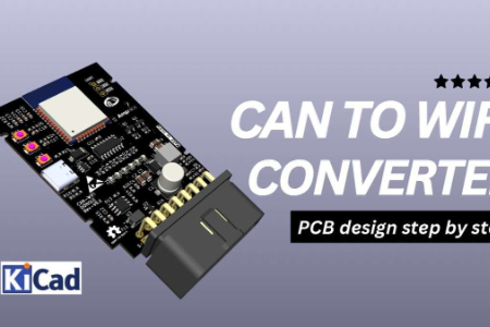
;}.c{fill:%23dbdbdb;}.d{fill:none;stroke:%23333;stroke-linecap:round;stroke-linejoin:round;}%3c/style%3e%3cclipPath%20id='a'%3e%3crect%20class='a'%20width='22'%20height='22'/%3e%3c/clipPath%3e%3c/defs%3e%3cg%20class='b'%3e%3cg%20transform='translate(1.375%202.251)'%3e%3cpath%20class='c'%20d='M7.563,9.224A20.661,20.661,0,0,1,18.8,8.265l-7.088,7.329-.922-.373-.023-3.312-1.389-.741-2.555.389-3.56,2.989-2,1.7s-.1-4.771,6.3-7.021'%20transform='translate(-0.5%200.249)'/%3e%3cpath%20class='d'%20d='M12.174.745l7.332,7.332a.834.834,0,0,1-.017,1.195L12.157,16.2a.833.833,0,0,1-1.405-.606V12.679a.844.844,0,0,0-.931-.832A11.108,11.108,0,0,0,2,16.74a.834.834,0,0,1-1.5-.576C1.132,9.59,3.786,5.4,9.942,5.066a.841.841,0,0,0,.81-.829v-2.9A.833.833,0,0,1,12.174.745Z'%20transform='translate(-0.5%20-0.5)'/%3e%3c/g%3e%3c/g%3e%3c/svg%3e)
Overview This repository contains the PCB design files for a CAN to WiFi converter based on the ESP32. The design allows seamless communication between a Controller Area Network (CAN) bus and WiFi, making it ideal for automotive and IoT applications.
Features
ESP32-based CAN to WiFi bridge
Supports CAN 2.0 communication
Onboard 12V to 5V buck converter for efficient power management
Designed using KiCad Compact and optimized PCB layout for reliable signal integrity
Project Structure /schematics/ – KiCad schematic files /pcb/ – PCB layout files /gerber/ – Fabrication-ready Gerber files /bom/ – Bill of Materials (BOM) /firmware/ – (Optional) ESP32 firmware for CAN-WiFi bridging
Getting Started
Clone the repository: bash Copy Edit git clone https://github.com/ampnics/CAN-to-WiFi-Converter-Dongle-/ Open the KiCad project files in KiCad v6 or later. Modify or generate Gerber files for PCB fabrication. (Optional) Flash the ESP32 firmware for testing.
Requirements
KiCad 6+ for schematic and PCB design ESP32 Development Environment (if using firmware) CAN Transceiver Module (e.g., SN65HVD230)
License
This project is licensed under the MIT License – feel free to modify and distribute!
Contributing Pull requests and improvements are welcome! If you find any issues, feel free to open an issue in the repository.
Author Developed by Md Ammar Maniyar (@ampnics). Reach out for collaboration or feedback!
;}.c{fill:%23555;}%3c/style%3e%3cclipPath%20id='a'%3e%3crect%20class='a'%20width='18'%20height='18'%20transform='translate(1543%202144)'/%3e%3c/clipPath%3e%3c/defs%3e%3cg%20class='b'%20transform='translate(-1543%20-2144)'%3e%3cpath%20class='c'%20d='M182.144,108.918a.7.7,0,1,1-1.407,0V98.083l-.033.027-.054.05-5.045,5.045a.7.7,0,0,1-1.041-.945l.046-.05,5.045-5.045a2.508,2.508,0,0,1,3.477-.031l.075.072,4.988,5.022a.7.7,0,0,1-.949,1.038l-.05-.046L182.21,98.2l-.066-.061Zm5.394-15.827a.7.7,0,1,1,0,1.407h-12.2a.7.7,0,1,1,0-1.407Z'%20transform='translate(1370.601%202051.909)'/%3e%3c/g%3e%3c/svg%3e "Back to top")