'/%3e%3c/svg%3e) Create Project
Create Project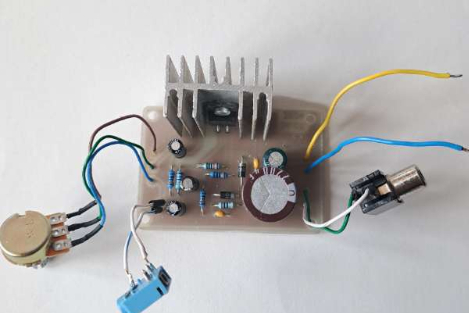
;}.c{fill:%23dbdbdb;}.d{fill:none;stroke:%23333;stroke-linecap:round;stroke-linejoin:round;}%3c/style%3e%3cclipPath%20id='a'%3e%3crect%20class='a'%20width='22'%20height='22'/%3e%3c/clipPath%3e%3c/defs%3e%3cg%20class='b'%3e%3cg%20transform='translate(1.375%202.251)'%3e%3cpath%20class='c'%20d='M7.563,9.224A20.661,20.661,0,0,1,18.8,8.265l-7.088,7.329-.922-.373-.023-3.312-1.389-.741-2.555.389-3.56,2.989-2,1.7s-.1-4.771,6.3-7.021'%20transform='translate(-0.5%200.249)'/%3e%3cpath%20class='d'%20d='M12.174.745l7.332,7.332a.834.834,0,0,1-.017,1.195L12.157,16.2a.833.833,0,0,1-1.405-.606V12.679a.844.844,0,0,0-.931-.832A11.108,11.108,0,0,0,2,16.74a.834.834,0,0,1-1.5-.576C1.132,9.59,3.786,5.4,9.942,5.066a.841.841,0,0,0,.81-.829v-2.9A.833.833,0,0,1,12.174.745Z'%20transform='translate(-0.5%20-0.5)'/%3e%3c/g%3e%3c/g%3e%3c/svg%3e)
Hi makers!
The presented audio amplifier is made using the TDA2030 integrated circuit. In the monophonic version, the amplifier, properly made, will present characteristics such as:
- output power in continuous sinusoidal mode: 15W/18W;
- musical power: 25W;
- input impedance: 150kΩ;
- voltage gain: 30dB;
- reproduced frequency band: 2Hz...30kHz;
- absorbed current: 1-1.3A.
At the output, the TDA2030 circuit has high current capability, with very low harmonic and connection distortions. Input sensitivity is 300mV. Power is provided from a well-filtered voltage source that can provide up to +35V at an absorbed current of 1.2A.
The voltage amplification of the assembly can be changed (when necessary) by juggling the values of resistors R4 and/or R5, as follows: Au = 1+ R5/R4. In the case of high amplification, there is a risk of oscillations, which leads to the failure of the basic component, namely the integrated circuit.
A load (acoustic enclosure) with an impedance of 4Ω is connected to the output. The TDA2030 integrated circuit is mounted on the radiator without electrical insulation. The total surface of the heat radiator used must be about 300cm2.
When put into operation, the assembly does not require any adjustment.
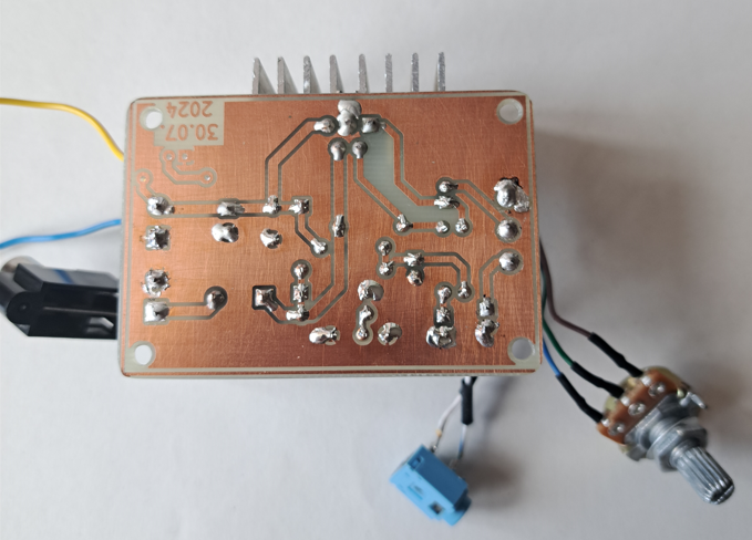
The PCB is made at a shop that deals with customizations (mugs, t-shirts, things like that), they have a powder printer (or something like that), and they helped me. Then, I etched it at home, drilled it and assembled it. Almost all the parts are recovered from electronics scrap boards.
I also have a 3D case design, but I don't think it's useful to you since you don't have the same parts as me, but you can use Gerber files for the PCB.
Have a great day!
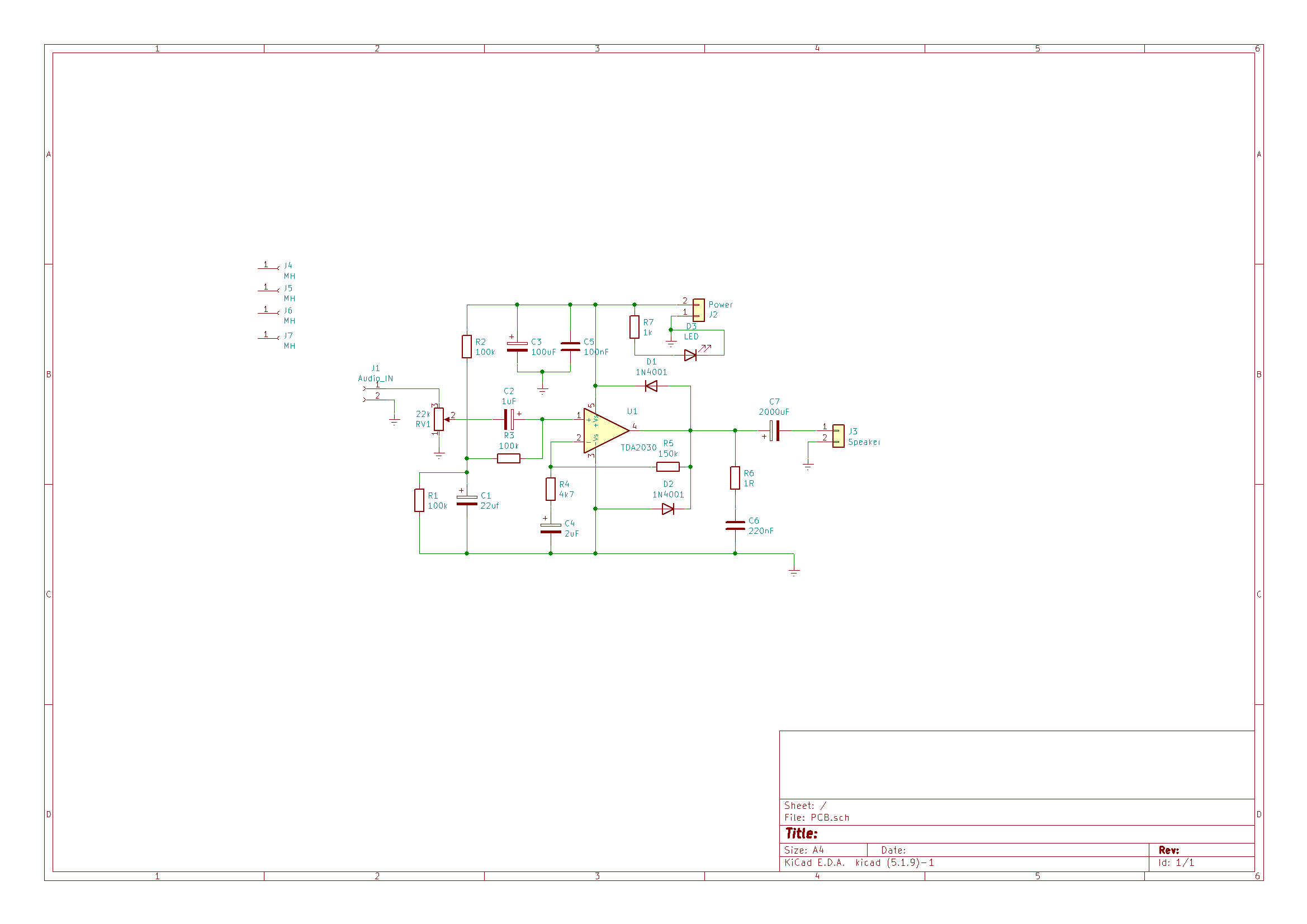
Electronic diagram:
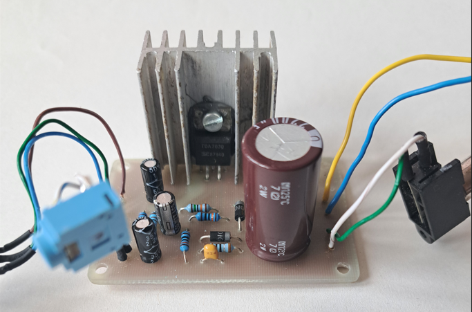
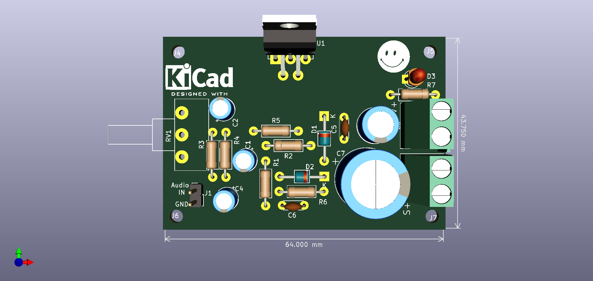
And assembly:
;}.c{fill:%23555;}%3c/style%3e%3cclipPath%20id='a'%3e%3crect%20class='a'%20width='18'%20height='18'%20transform='translate(1543%202144)'/%3e%3c/clipPath%3e%3c/defs%3e%3cg%20class='b'%20transform='translate(-1543%20-2144)'%3e%3cpath%20class='c'%20d='M182.144,108.918a.7.7,0,1,1-1.407,0V98.083l-.033.027-.054.05-5.045,5.045a.7.7,0,0,1-1.041-.945l.046-.05,5.045-5.045a2.508,2.508,0,0,1,3.477-.031l.075.072,4.988,5.022a.7.7,0,0,1-.949,1.038l-.05-.046L182.21,98.2l-.066-.061Zm5.394-15.827a.7.7,0,1,1,0,1.407h-12.2a.7.7,0,1,1,0-1.407Z'%20transform='translate(1370.601%202051.909)'/%3e%3c/g%3e%3c/svg%3e "Back to top")